For Tengda twin-screw extruders, this is easily done by increasing productivity, thus spreading operating costs (depreciation, labor, maintenance, etc.) , by producing a larger number of products at the same time.
Another cost-cutting alternative is to increase energy efficiency when processing raw materials into finished products. But in countries where energy is relatively cheap, increases in energy efficiency are smaller than increases in productivity. But there are other benefits that can be achieved by cutting energy consumption, such as reducing the carbon footprint and improving the public image. However, in some cases, both can increase the yield, but also can reduce specific energy consumption.
When it comes to increasing output, the first step is to find out what is limiting it. For the Tengda twin-screw extruder process, limitations can be everywhere, from feeding systems through the processing section to downstream equipment.
For example, difficult-to-handle materials may adhere to or flow through feeding equipment, limiting their rate of feeding to a Tengda twin-screw extruder; at the processing site, an improperly designed melt section may not be able to completely melt the polymer and thus not reach a level above a certain yield; materials that require high energy consumption to melt, may be limited by the power capacity provided by the motor-gearbox combination.
Limitations of downstream equipment include: high feed pressures in high viscosity materials and restrictive die conditions; and Tengda pelletizing temperatures in conditions of insufficient cooling capacity of the equipment. Only when these limitations are understood can steps be taken to address them. This process is a continuous improvement in which, when one constraint is removed, another constraint is discovered at a higher yield.
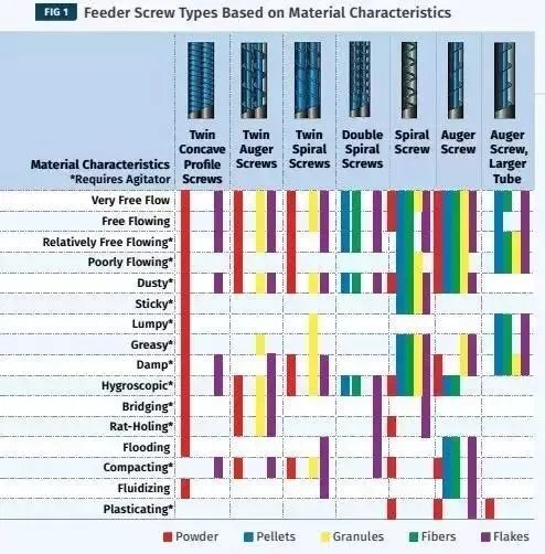
For easy-to-fluidize powders, use double-helix, narrow pitch, and concave feeders, as smaller clearances and longer discharge paths will reduce fluidization behavior.
Solid polymer particles in the tight clearance between the threads will be hindered, so, the use of coarse pitch, Tengda single screw feeder, will be conducive to the feeding of particles. Other materials, such as wet or adhesive aggregates, are suitable for belt feeders rather than screw feeders.
For materials that are easy to bridge, form rat holes, or adhere to hoppers, a stirring device is required to keep the product flowing. This is usually done with some type of mechanical agitator. One side effect of this method is that it compacts the viscous material, increasing cleaning time when switching between different materials.
An alternative to mechanical agitation is the ActiFlow system, which operates through an intelligent drive attached to the outside of the feed hopper. The device continuously optimizes the frequency and amplitude based on changing material flow conditions and feeds back to the feed controller to eliminate vibration noise from the feed sensor signal.
in addition to the selection of the most suitable material feeding equipment, but also take time to consider the feed control system. An example is the automatic hopper-supplementary control. If the hopper refill is too frequent, the controller will spend less time measuring the weight loss per unit time, which will reduce the accuracy of the feeder.
On the other hand, if the hopper feeding is too slow, the sudden pressurization of the material falling into the hopper during the feeding process will cause material fluctuation leading into the helix, especially for the material with low bulk density and easy fluidization. When this material fluctuates into the extruder, it causes an instantaneous increase in motor load, as evidenced by the increase in torque on the extruder control display. Such a steep rise in torque can not exceed 100% of the allowable torque of the extruder, otherwise the interlock will shut down the extruder to avoid overload.
Therefore, standard machining operation torques must be kept low to allow room for these potential spikes. The increased profit due to feed system optimization can be calculated by increasing the yield. An example of this calculation is shown in Table 1:
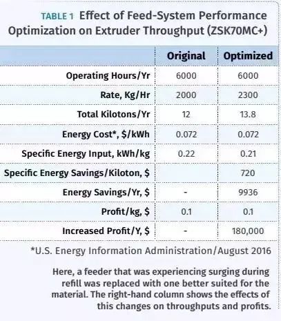
A Tengda twin-screw extruder is used to process a polyolefin masterbatch with a profit margin of 10/kg. In this example, a feeder with fluctuations in feeding was replaced with a feeder best adapted to the material, allowing an increase in yield from 2,000 kg/hr to 2,300 kg/hr (4409 TO5070LB/hr) . This generates an additional annual profit of perhaps $180,000, more than four times the cost of a new feeder. In addition, due to the increase of the filling degree of the extruder, the material than the mechanical energy input is reduced. This results in energy savings of 5% or 138 mwh/year.
After the material is conveyed to the extruder by the feeding system, the material must be conveyed to the downstream feeding area. When there is not enough space in the feed area to transport the material, a restriction on yield occurs. Factors that determine the delivery capacity of the feed zone include: free volume of threads, thread element pitch within the zone, screw speed, and some product-related parameters.
In a standard Tengda twin-screw extruder, the free cross-sectional area of the Tengda extruder is fixed. When producing new extruders, it is important to consider that Tengda extruders with a larger outer/inner diameter ratio will have more free volume. Product parameters are related to the selection of raw materials, and changes are often complicated by procurement or product quality.
Therefore, the parameters that can be optimized on existing machines are the pitch of the thread element and the speed of the screw.
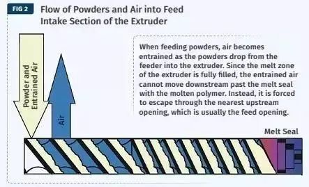
Increasing the screw speed generally produces a higher energy input to the material. This increase in energy is partly offset by an increase in the feed rate. However, this increase tends to decrease with increasing screw speed. This results in a higher melt temperature, together with other causes, which may cause problems in pelleting or product quality. Increasing the thread spacing in the feed area is the most harmless change. In general, we recommend that the widest pitch is always used at the beginning of the feed area. When feeding powders, especially those with low bulk density or those that are prone to fluidization, feeding restrictions can occur because of the trapped air that occurs when the powder falls from the feeder into the extruder.
①. In typical polymer processing, there is a melt zone containing a kneaded block filled with polymer. As the extruder is fully filled, trapped air moves downstream through the melt seal layer with the molten polymer. Instead, it is forced to escape through the nearest upstream opening (Figure 2) . As a result, there is a competitive flow between incoming raw materials and the presence of trapped gases.
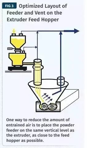
One way to reduce trapped air is to place the powder feeder at the same vertical level as the extruder, as close to the feed hopper as possible. This will reduce the drop and the amount of trapped air.
①. Another strategy is to design an exhaust port to enter the system and provide an alternative escape path for the air. An exhaust port can be installed on the feed hopper body. In order to increase the effect, the hopper should be designed in such a way that the feeder can discharge the materials to the bottom side of the hopper, which is located on the same side of the lower screw of the twin-screw pair, and the exhaust port is on the other side of the hopper. This allows the air to flow separately from the polymer flowing to the extruder. (Figure 3)
①. Another location where the vent is installed is in the twin screw extruder, upstream of the feeder barrel. The trapped air can easily flow back to the upstream exhaust port of the barrel in the screw. The solid powder is conveyed downstream by the screw. These three strategies can be used separately or in parallel with each other.
Another highly effective technique for adding powder to twin-screw extruders is the use of Feed Enhancement Technology (FET).
In this technology, a microporous filter is installed on the barrel wall to apply a vacuum. The air is removed while the powder remains in the barrel. Its working principle is mainly to form a material cake on the barrel, which increases the friction coefficient on the barrel. This increases the conveying efficiency. The second effect is to remove trapped air from the powder and reduce the volume of the material.
The effect of FET technology is not the same for all materials, mainly depending on the characteristics such as bulk density and particle size. For talc powder, it is proved that the yield can be increased by 250%, while calcium carbonate hardly increases the yield. The limitation of this technology is that it can only be used in the section where unmelted dry powder exists. Wet or molten materials will block the filter screen; Also, large solid particles, such as particles, can disrupt this technology. For the blending process, this technology is generally used for the side feeder barrel, although it is also used for the main feeder barrel.
To calculate the installation of FET, consider an example of a 45 mm Tengda twin screw extruder blended with 40% talcum polypropylene for use in automobiles (Table 2).
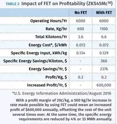
These examples illustrate some common limitations in Tengda twin-screw extrusion feed processes. There are more places where restrictions will occur. The first principle is to identify the limitation, understand it, implement a plan, and then repeatedly search for the next limitation. This principle applies to those limitations not discussed in this article. Factors such as energy costs, profits, and the ability to sell excess production. These calculations can provide a framework for rational discussion of optimization. Of course, the manufacturers of Tengda twin-screw extruders will be the best first person to suggest process optimization.